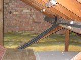
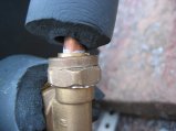
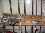
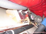
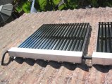
The return (cool water back to panel), with a couple of nogginson the purlin to hold it up. The panel-holding noggins and straps are also visible.
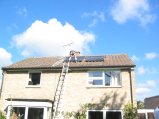
The finished job with the walkway back in place.
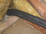
The pipes passing out of the loft down into the airing cupboard. You can see the only join I had to make so far (because 10m 10mm of pipe wasn't enough - doh!). Later on I glued the armaflex together but forgot to do upthe compressionjoint properly so lot of water came out the end of the insulation. I was impressed by how well the glue worked through (normal armaflex glue sticks HT insulation just fine).
The PHE (plate heat exchanger) plumbed in. The solar loop flow pipe has a dip in it to stop thermosiphoning at night when the tank is hot
This shows the PHE fitted in relation to the hot water tank. It is attached at the coldfeed pipe and the vent pipe. This is supposed to thermosiphon sufficiently to move heatinto the tank. This arrangement is something of an experiment to see how well it works with an existing tank.
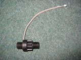
Swissflow SF800/2 flow sensor. Kindly donated as a sample by swissflow for testing in solar loop context.
This is the business part of the plumbing. From bottom right (which comes out of the PHE), we have drain cock, pump, flowmeter, filling point, check valve with bypass, then T off to pressure guage and EV. Solar return is out the top. The pump is the Davies-craig 'EBP' which provides flow rates from 2-24l/m (2-24W), so should be lower consumption than a conventional CH pump.
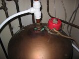
Completed solar loop plumbing in situ. The green thing is the garden sprayer pressuriser/filler. The round tin is the catch tank for if the PRV releases any overpressure (the design it such that it never should). The EV piping goes down a bit first then back up, again to stop thermosiphoning of very hot liquid into the EV which might damage the diaphragm.
The expansion vessel. It was going to be in the cupboard opposite this one, to give more room for the tank, but I've temporarily plumbed it in here for now as it was easier. If/when a huge tank goes in here it will be moved. This vessel is 18l which should allow sufficient expansion that the system never vents, even in full stagnation.
Damn- I have a leak.
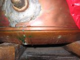
Somewhere in all this (probably unscrewing the drainock in order to add the PHE at the top of this photo, as I needed a big spanner and lots of force to get it out) my tank sprang a leak. It's actually coming from a pinprick just to the right of the boss, not (as it looks) from the bottom of the silvery bit.
This was comedy attempt at a fix #1. As fibreglass is all goopy I thought it just might seal without draining down. It didn't. I'm losing about 200ml a day and now collecting it in a tub so I can afford to not worry about this too hard, at least for a bit.
I spent ages trying to get the solar loop to hold pressure. Adding inserts to the 10mm pipe helped a lot and some La-co PTFE thread seal goop. Unfortunately that allowed me to overtighten this fitting and burst it. Had to go shopping for a new one. (whcih is 5 times as expensive from Ridgeons as from BES - although the new one didn't break)
This shows the airing cupboard layout on the solar side. The tank is in the process of being removed.
Removing the tank so that the leak at the bottom can be fixed. Getting the last bit of water out was a chore - it needed complete disconnection and removal so the tank could be tipped over. Also turns out it has about 12cm of limescale in the bottom.
Laco heat stik (meltable epoxy) did the job on my leak. This is good stuff. I did scorch the washer/hemp n the socket though which weeps a bit instead now. It'll do for now.
Took the oppoertunity of the draindown to add a boiler buddy to the CH circuit. The piping has gone quite orange with deposits in the 6 months it's been installed.
Removing and replacing the tank made it spring more leaks! It's clearly not in very good nick. Where the top pipe flexed 3 more holes appeared. Drain down again (only part-way this time) and some more epoxy did the trick.
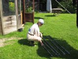
Finally the pressure-leak rate is brought down enough put in some tubes! Tess is putting heat-paste on the ends.
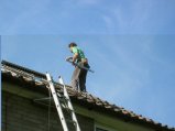
Carrying a tube onto the roof
Fitting tubes. A very quick and easy job in comparison to the plumbing. The controller is not yet finished so we run for a few days on manual control (a pump switch).
The controller is now working on breadboard, so it is installed and tests OK.
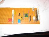
The breadboard is prone to wires falling out so the design is transferred to veroboard. The I2C to 1-wire chip is inthe middle. Pump relay is the blue box.
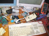
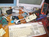
This mess is my controller. Balloonboard with CUED IO board inthe perspex box, and my IO board plugged into thte I2C bus. The grey box is a USB to ethernet adaptor to connect it to the net. Some proper mounting is needed here, and a display.
It takes more than 6 months to tidy this up properly - it's surprisingly reliable even in this state.
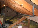
This pic shows the insulation round the plate heat exchanger. There are still some pipes to insulate properly. I used PUR foam as I had offcuts to hand, but it's fiddly to get in place because it is rigid, and heat probably gets out through the gaps to some degree.
In August we eventually get round to swapping the duff reflector and tube at eco-nomical (who even gave us a spare tube for our trouble), so now we can populate the 2nd panel with another 20 tubes.
Shiny!
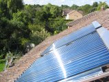
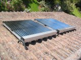
Overview of newly-installed panels
You can see the spacing and insulation between the two panels here.
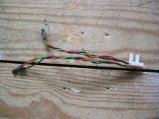
This is a pair of 1-wire temp sensors for attaching to the PHE. I settled on these molex-alike connectors in the end as they are cheap and versatile. Works well, but crimping the cables is tedious.
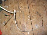
An assembled segment of 1-wire sensors. Two pairs of sensors and a short run of cables. These four go on the PHE.