Solar Thermal installation

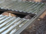
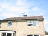
The bare roof, before I started.
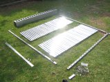
The solar panel parts, ready for bolting together. This panel, from eco-nomical.co.uk has two fixed mylar-covered reflector panels. On the left is the stainless steel strap which holds it to the roof.
First set up some ladders. I added a block to my standoff to make it deep enough. The observant will notice that that's not a proper roof ladder - it's a multi-purpose stepladder/decorating platform. It just makes getting to the chimney to secure some ropes less dodgy. My roof slope is only 30 degrees, and the tiles are thick and strong, so once the gravelly bits are brushed off, moving about on the roof is easy and doesn't really need a roof ladder at all.
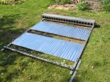
Assembled panel
Ladders in place and tied to chimney stack.
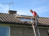
Getting the first panel onto the roof. I used a pulley-jammer to ratchet it up, with Tess hauling and me steering. I protected the manifold with its cardboard box. This bit is reasonably entertaining, and it catches on the tiles in a thoroughly awkward fashion.
Look, a panel and a Wook.
This is where I realise the wavy tiles are a bit tiresome to fit panels over. Getting the panel to sit properly and reasonably rigidly, with the straps going under tiles at a sensible point (not on the steep side of the tiles) and the pipes going through the roof co-inciding with peaks involves a lot of humming an haa-ing. Took the best part of 3 days to get it all sorted.
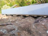
The panel is actually resting on the reflector panels, rather than the main side-struts.
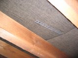
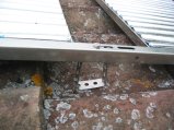
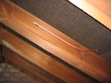
This is the stainless strap after it is poked through in about the right place to see where it comes out on the roof.
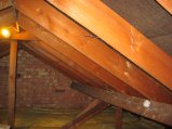
The strap in a more general loft view.
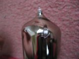
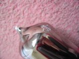
This tube appears to have been bashed and has a nasty-looking crack which I suspect will let air in eventually.
And again. The nice people at eco-nomical agree that's no good and will replace it.
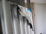
The mylar wasn't glued down on one of the reflective panels, so it tore off along with the blue protective sheet. Seems to be a manufacturing problem (glue ran out at the end of the roll perhaps?). The other 3 reflectors were fine.
Fine customer service from eco-nomical who agreed to replace it forthwith.
Preparing to hoist the second panel.
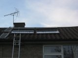
We now have two (slightly wonky) panels on the roof. Much faffing follows.
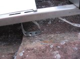
This was my eventual solution for getting the panel height correctly adjusted and having them supported convincingly by the main struts: bend the stainless strip into 'feet'. Bit of a game to adjust, but it seems to work quite well.
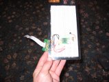
This is the prototype sensor interface board. I2C to 8-channel dallas 1-wire chip, with a couple of test temp sensors on one channel. It's not working yet.
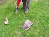
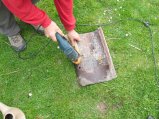
I drilled a hole in my roof! Note the nice 'arbor' for the diamond core drill made from a bit of wood, and the expensive water-cooling system. All works very well. Nice neat holes in implausibly thick (28mm) tiles. Somewhat easier to bring tiles down that to bring power, drill, cooling system and assistant on to roof, although we had to do that for one hole as the tile wouldn't easily come off.
This is how the arbor works.
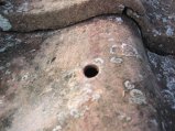
Hole, miraculously in the right place. 15mm hole allowing room to silicone around 10mm pipe.
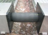
To get the supports and pipes properly spaced meant that the two panels needed to be slightly further apart than 'as close as possible'. So there are two 22mm compression couplers under there with a very short bit of pipe. I managed to do it with an unsplit piece of Armaflex insulation in place, which was a struggle, but does look neat.
10mm pipe now in place. The fitting is 22-15 elbow with a 15-to-10 reducing olive in it to take the 10mm pipe. It turns out to be tricky to make this seal (this one was OK, but both at the other end leaked), so either lots of pipe sealant or (better) 10mm pipe inserts are a good idea.
Support leg in the middle of the panel strut. I'm getting neater at making them by now.
The pipework covered with armaflex HT (high temp) insulation, before it was glued together. I've gooped the bottom of the insulation to the tiles so most water doesn't even get near the hole.
First hole at the other end - this is the hot return.
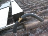
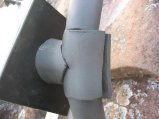
This shows the hot return (lower pipe) and the air bleed (upper pipe) going into the loft for (relatively) convenient bleeding. You can also see the strap going under the tile (this tile refused to sit as flat as the others, but it still seems to keep the water out).
Add insulation and tighten up the joints.
It's hard to cut this stuff neatly even with a really sharp knife. I hope this'll look better when it's finished!
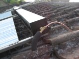
The air bleed inde the loft. All-brass radiator bleed valve so it can't melt.
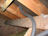
The flow pipe, and panel-holding noggin.
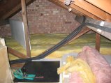
The flow and return pipes going down through the loft to the airing cupboard. I've had to disassemble the loft walkway (polystyrene and planks) to fit this.